EasyFrames, Feet and Footings
EasyBases Aluminium profiles create a lattice spanning the outer frame, providing an interlacing support for the building floor or flooring tiles. Precision riveted fixings and pre-fitted corner hex screws allow for simple ‘slot together’ assembly in minutes.
Should you require, fixed or adjustable feet can be can be added at any point on the surrounding frame or cross beams. As every installation differs, we can advise on the needs of your project to help you ensure your building is supported appropriately.
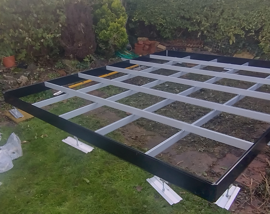
The photographs to the right demonstrate two differing uses of our feet. The first uses load-spreading Aluminium feet to support an old shed, simply using the customer’s old masonry and well bedded in paving. The second, unfortunately low-res image, demonstrates the support of a greater load by the combination of stillage feet supported on concrete posts, above a very uneven surface.
▀█▀▀▀▀▀▀▀▀▀█▀▀▀▀▀▀▀▀▀█▀
How strong are EasyBases?
We are often asked how much weight EasyBases can hold and of course rather than enter into piece of string debates, would suggest exploring the project you are considering with us if it involves extreme load bearing.
Frames and feet have been stress tested individually and combined, to ensure they will exceed normal usage expectations.
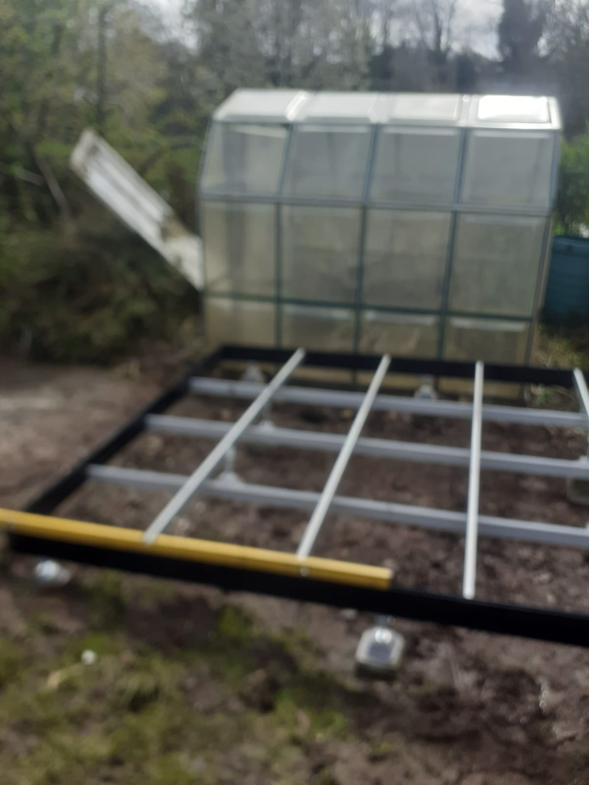
As an example, a test that we can do but would not advise was to build one of our concrete shed/greenhouse developments on an EasyBase as we worked on the project through last year.
The image shows the structure in February 2025, still sitting on 10 stillage feet on an unprepared grass base. The entire structure, with shed and tiles combined exceeding 1,000Kg.
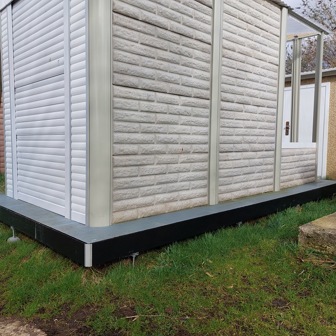
Below is a demonstration using just two short lengths of frame mounted on low profile feet, supporting 1,280Kg of concrete panels.
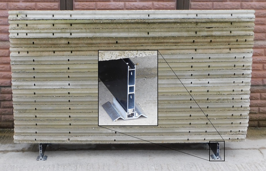
▀█▀▀▀▀▀▀▀▀▀█▀▀▀▀▀▀▀▀▀█▀
What about all these feet?
The majority of the feet we offer are intended to serve the purpose of providing precise levelling capabilities to serve an ever growing number of scenarios. It can hardly be said a purpose-built concrete base will need adjustable feet. In such cases, the needs of damp prevention, cold bridging and including an air gap, may still suggest the use of an EasyFrame alone.
Adjustable feet can be attached both during and after installation due to the screw-free insert design. We see the addition of more feet to be an additional option because if the frame is installed and levelled correctly, further adjustment should not be necessary. The purpose of the insert design was to simplify assembly, rather than for post-install adjustments.
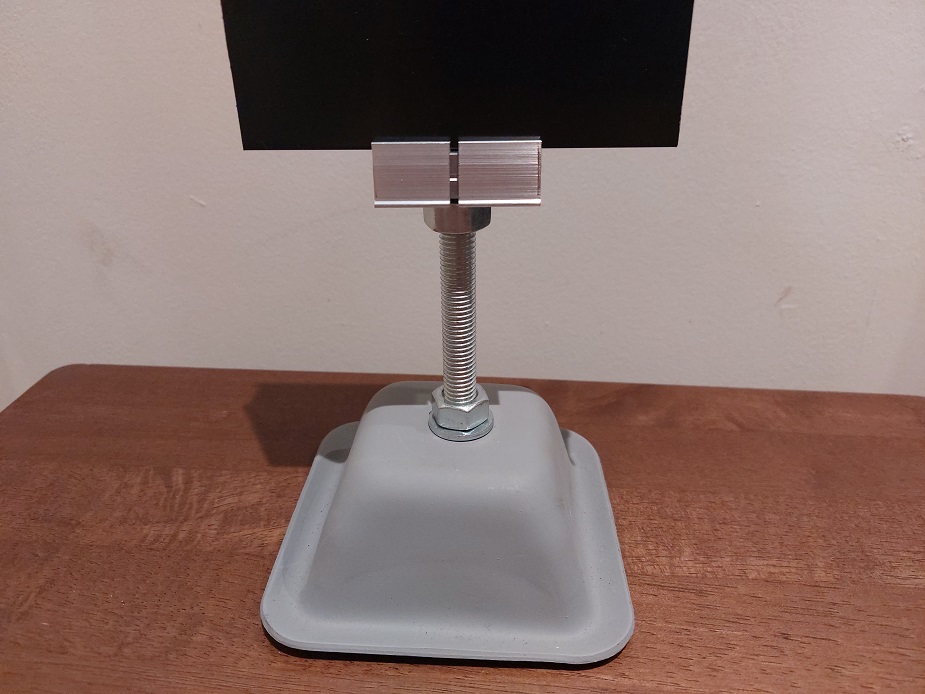
The first image to the right demonstrates the ‘stillage’ or pyramid foot attached with a 100mm M12 bolt to our screwless insert.These are the tallest of our feet and allow greatest adjustment range.
Sourcing heavy duty industry standard steel stillage feet, we apply the shown finish at our factory. Each foot can take a load over one ton.
As for all such feet, adjustment to desired height can be achieved by a combination of bolt length and nut movement.
▀█▀▀▀▀▀▀▀▀▀█▀▀▀▀▀▀▀▀▀█▀
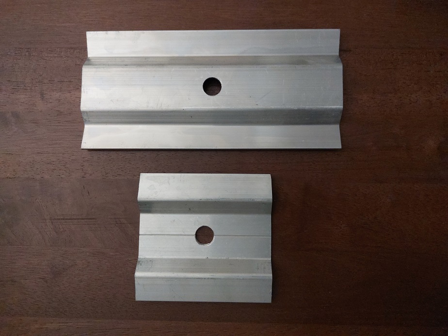
The second image displays our load-spreading Aluminium feet in 100 and 200mm lengths. These can be used to generate a greater spread of load on the installation surface but we must advise against trying to use these to mitigate an inappropriately weak or soft substrate.
An example of an appropriate use for these feet is shown here.
▀█▀▀▀▀▀▀▀▀▀█▀▀▀▀▀▀▀▀▀█▀
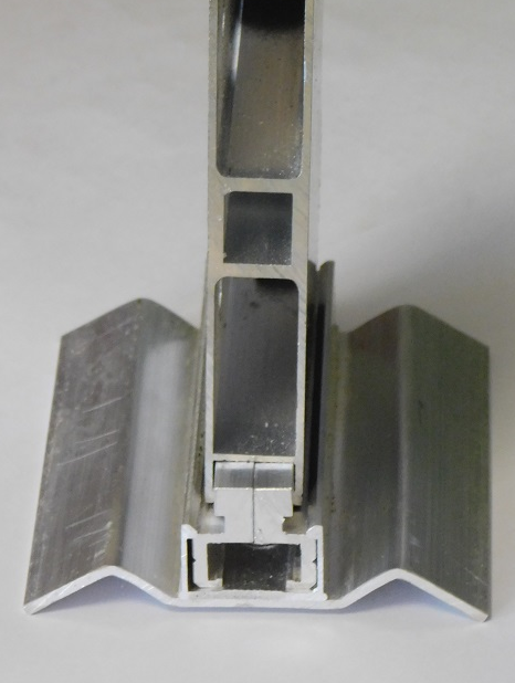
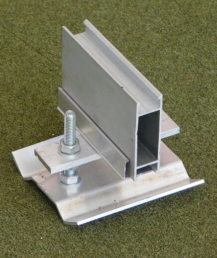
The third image is the first of our new designs for 2025. Answering the need for a foot but with the lowest possible profile height, the ‘low profile foot’.
Using the same insert design but without the bolt attachment, allows us to bring the height of a structure down while still benefitting from the load distribution of the Aluminium foot.
Although when attaching feet on all four sides of a frame, there is little chance of slippage, we can offer inserts with screw fittings to lock the foot in place.
▀█▀▀▀▀▀▀▀▀▀█▀▀▀▀▀▀▀▀▀█▀
Our final image is the second of our new feet for 2025, an inner support foot. We would classify this foot as somewhere near to a custom development, resulting from a request to provide increased load bearing in larger structures by attaching these feet to the inner cross-beams.
We have included it as we can supply them and although the use cases for these are less common, we are committed to developing new methods for fitting our frames to suit a widening range of scenarios.
▀█▀▀▀▀▀▀▀▀▀█▀▀▀▀▀▀▀▀▀█▀
On the Subject of Ground Screws
Sitting right in the middle of debate and opinions regarding what base types to use, is the topic of ground screws. Some swear by them, others about them!
EasyBases approach from a ‘surface agnostic’ position, by talking to many types of professional, we have already developed two new feet styles for possible scenarios that have been considered and fed back to us. The potential adaptions our Aluminium extrusions allow, lend themselves to expanding EasyBases’ applications.
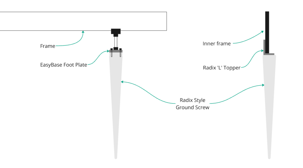
Following some conversations regarding pre-fitting EasyBases frames to buildings that could be dropped in by crane onto ground screws, we looked at some well respected ground screw manufacturers’ product ranges. The diagrams below represent some conceptual representations of our next possible developments for this year.
The diagram on the left shows a method for installing a frame by attaching our inserts and bolt to a foot plate fixed to the ground screw.
On the right, using ‘L’ brackets from Radix’s own range, a set of ‘pins’ can be formed in a rectangle to be used in the context of dropping a frame around the four axes ‘L’ brackets, thus creating a precisely fixed base potentially without the need for any bolt or screw fittings. Would certainly prove the ground screws were aligned.